


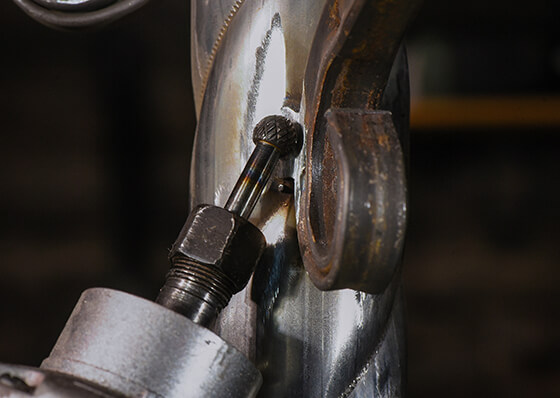
Carbide burrs don’t have one ideal machine setting for every job. Effective cutting depends on balancing cutting speed and feed rate for the burr diameter, workpiece material, tool geometry, and conditions at the point of contact.
Settings that don’t suit the application can contribute to poor chip evacuation, excessive heat, chatter, premature wear, chipping, or clogging. Understanding how speed and feed interact gives you a better starting point for correcting these problems without simply turning the RPM up or down.
How Cutting Speed and Feed Rate Affect Carbide Burr Performance
Cutting speed and feed rate work together to determine how effectively a carbide burr removes material. Cutting speed is commonly expressed as surface feet per minute (SFM), while RPM measures how many times the tool rotates each minute. Feed rate describes how quickly the burr advances through or across the workpiece.
RPM isn’t interchangeable with SFM because cutter diameter affects the relationship between them. The goal is to maintain effective cutting and chip evacuation without placing unnecessary thermal or mechanical stress on the burr.
Start With Surface Feet per Minute and Burr Diameter
Surface feet per minute describes the speed at the outside diameter of the cutting tool. A smaller burr generally needs a higher RPM than a larger burr to achieve the same SFM.
A standard machining relationship is:
RPM ≈ (3.82 × SFM) ÷ tool diameter in inches
This formula shows why a single RPM recommendation can’t apply across different burr diameters. Published cutting data may provide a target surface speed, but diameter still has to be considered when converting that value into spindle RPM.
Manufacturer speed charts should therefore be treated as guidance for the specific tool and application, not copied from an unrelated burr size or setup.
Match Cutting Speed to Burr Diameter and Tool Construction
Recommended rotational speeds commonly decline as burr diameter increases. Published carbide-burr guidance may also differentiate among tool constructions, including solid-carbide products and carbide heads mounted to steel shanks.
Tool projection deserves similar attention. Long-shank carbide burrs can be less stable because more of the tool extends from the holder. Manufacturer guidance calls for reduced rotational speeds on long-shank variants and stresses the importance of rigid clamping.
For reliable tool performance, start with the guidance for the exact burr diameter and construction you’re using rather than extrapolating from another tool.
Adjust Machining Speed for the Workpiece Material
The workpiece also affects suitable machining speed. Hardness, toughness, heat generation, and a material’s tendency to smear or load onto the cutting edges can change how a burr behaves.
Materials prone to loading need particularly effective cutting action and chip evacuation. If material begins packing between the cutting edges, the burr may rub rather than cut efficiently, which can generate additional heat.
That makes material only one part of the decision. Burr geometry, diameter, engagement, speed, and the stability of the setup should be evaluated together.
Set Feed Rate to Maintain Effective Chip Formation
Feed rate is the rate at which the burr advances across or into the material. It needs to remain balanced with rotational speed so the cutting edges can remove material and clear chips effectively.
Feeding too lightly can promote rubbing rather than productive cutting. At the other extreme, excessive engagement or chip load can interfere with evacuation and place greater stress on the cutting edges.
Suitable cutting feeds depend on the material, burr geometry, amount of engagement, machine or hand-tool stability, and desired removal rate. Don’t automatically respond to poor cutting by slowing the feed dramatically. Prolonged contact without effective material removal can contribute to rubbing and heat buildup.
Watch for Chipping, Chatter and Excessive Heat
Chatter, vibration, rough cutting, unusual heat, rapid edge wear, or carbide chipping can indicate that the speed and machining feeds need attention. They don’t automatically prove that RPM is the problem.
| Symptom | Possible Speed/Feed Cause | Other Factors to Check | Adjustment Direction |
|---|---|---|---|
| Chatter or vibration | Feed too light or unsuitable speed | Tool projection, holding stability, burr selection | Adjust one variable and reassess stability |
| Excessive heat | Rubbing or prolonged contact | Material, engagement, burr geometry | Restore effective cutting action |
| Poor chip evacuation | Feed and speed poorly balanced | Cut geometry, material loading | Reassess feed, speed, and engagement |
| Chipping | Excessive cutting stress or unstable action | Projection, holding, tool condition | Reduce stress and confirm recommended speed |
Change one variable at a time where practical. Controlled adjustments make it easier to identify what actually improves the cut.
Prevent Carbide Burrs From Clogging
Clogging, or loading, occurs when removed material collects around or between the burr’s cutting edges instead of clearing away.
It isn’t simply an RPM problem. Workpiece material, burr geometry, cutting speed, feed rate, engagement, and chip evacuation all influence loading. Maintaining effective cutting action rather than prolonged rubbing can help limit the heat and material buildup that contribute to clogging.
If a burr begins loading, assess the complete setup before simply increasing RPM. The cut geometry should also suit the material and application.
How to Dial In Speeds and Feeds Without Damaging the Burr
Start with verified manufacturer guidance for the exact carbide burr, particularly its diameter, construction, and intended material. Confirm how the recommended cutting speed translates into RPM instead of assuming the machine’s maximum speed is suitable.
A practical setup sequence is:
- Identify the workpiece material and burr type.
- Confirm burr diameter, construction, and manufacturer speed guidance.
- Set an appropriate initial speed and feed, then observe chip evacuation, vibration, heat, finish, and tool condition.
- Adjust one variable at a time while watching how cutting behaviour changes.
Long projection or an unstable setup may require a lower operating speed. If cutting deteriorates, don’t compensate by forcing the burr harder into the workpiece.
Why the Right Speeds and Feeds Improve Tool Performance
Properly matched speeds and feeds support stable material removal and allow chips to clear more effectively. They also reduce avoidable conditions such as rubbing, chatter, clogging, excessive heat, and unnecessary stress on the cutting edges.
Tool performance still depends on more than machine settings. Burr diameter and geometry, material, engagement, tool holding, machine condition, and operator technique all affect the result.
Clarkson-Osborn carries carbide burrs as part of its cutting-tool range and provides application-focused consultations. Our technical team can help customers and distributors evaluate tooling requirements when selecting a cutting tool for a specific project.
Get Help Choosing Cutting Speed for Your Application
Effective cutting speed comes from balancing RPM, feed rate, burr diameter, workpiece material, and the operating conditions rather than applying one setting to every job. Chip formation, vibration, heat, clogging, and overall cutting behaviour can provide useful signs that the current parameters need adjustment.
Clarkson-Osborn Tools provides cutting-tool consultations and application recommendations to help customers identify suitable tooling for their requirements.
Reach out to Clarkson-Osborn Tools today at (905) 453-4680, email us at sales@clarkson-osborn.com or click here to get in touch online.
Frequently Asked Questions
How do I calculate RPM from surface feet per minute?
Use the standard relationship:
RPM ≈ (3.82 × SFM) ÷ tool diameter in inches
Diameter matters because two carbide burrs running at the same surface feet per minute require different RPM values when their diameters differ. A smaller diameter generally requires more RPM to reach the same surface speed.
Should a smaller carbide burr run faster than a larger one?
Generally, a smaller-diameter carbide burr requires higher RPM than a larger burr to achieve the same surface speed. That doesn’t mean diameter should be the only factor used to select RPM.
Follow the speed guidance for the specific burr, material, construction, and application rather than choosing a setting from diameter alone.
Why does my carbide burr keep clogging?
Material characteristics, burr geometry, cutting speed, feed rate, chip evacuation, and rubbing can all contribute to material loading between the cutting edges.
Instead of treating higher RPM as a universal fix, check the entire application. A different feed, level of engagement, cutting geometry, or operating speed may be needed.
Can running a carbide burr too slowly cause problems?
An unsuitable relationship between speed and feed can encourage rubbing, chatter, ineffective cutting, and heat buildup. The correct adjustment depends on the burr diameter, material, feed, engagement, and stability of the setup.
Use the manufacturer’s recommended operating range as the starting point rather than assuming slower is always safer.
Why do long-shank carbide burrs need different speed settings?
Additional tool projection affects stability and can increase the risk of vibration or bending. Published manufacturer guidance therefore specifies reduced rotational speeds for long-shank carbide burrs compared with standard-shank tools.
Always follow the operating and safety recommendations provided for the exact long-shank burr you’re using.
