


Blind and through holes create different requirements for chip evacuation, thread depth, and tap geometry. Choosing a tap based only on thread size can result in chip packing, poor thread quality, premature wear, or a broken tool.
For machinists, fabricators, maintenance personnel, and purchasing teams, selecting the right tapping tools means looking at the complete application. The physical hole design is the logical place to start.
Choosing Tapping Tools for Blind and Through Holes
The correct tapping tool depends partly on where the chips can travel and how much usable thread the finished part requires. A blind hole contains chips within a closed space, while a through hole gives chips a path beyond the bottom of the workpiece.
That distinction matters, but it isn’t the only selection factor. Hole depth, workpiece material, machine setup, coolant delivery, tap geometry, and thread specifications all affect performance. No single tap style is suitable for every material or operating condition.
Understand the Basic Difference Between Blind and Through Holes
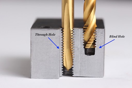
A blind hole stops within the workpiece instead of passing through it. The closed bottom limits the available space for chips, coolant, and the tap’s chamfered lead.
A through hole extends through the full thickness of the workpiece. Chips can often move beyond the bottom, although the material, tool design, and machining conditions still determine how easily they evacuate.
A simple side-view diagram can help illustrate the difference: one hole ends inside the part, while the other opens on the opposite side.
Account for Thread Depth and Bottom Clearance
Drilled-hole depth, tap penetration depth, and complete thread depth are not interchangeable measurements. Before a tap produces full-profile threads, its chamfered lead must enter the hole and begin cutting gradually.
A blind hole therefore needs clearance below the final complete thread. That extra space accommodates the tap lead and provides room for chips. Trying to machine threads too close to the bottom can increase torque, damage or incomplete threads, or cause the tap to bottom out.
Confirm the part drawing, required thread depth, and available drilled depth before selecting the tap.
Match Chip Direction to the Hole Type
Chip evacuation is one of the clearest differences between blind-hole and through-hole tapping. Chips trapped at the bottom of a blind hole may be recut or compacted, increasing torque and damaging the finished thread.
Certain geometries direct chips upward, away from the closed end. In a through hole, a chip-forward design can move material ahead of the cutting action and out through the bottom.
Workpiece material also changes chip behaviour. Ductile materials may produce long, continuous chips, while other materials create shorter segments that evacuate differently.
Use Spiral Flute Taps for Appropriate Blind-Hole Applications
Spiral flute taps lift chips upward through the flutes and away from the bottom of the hole. This chip direction can make them useful for many blind-hole applications involving materials that produce continuous chips.
Performance still depends on the flute angle, helix design, substrate, coating, workpiece material, and machine conditions. A spiral flute tap shouldn’t be treated as an automatic solution for every blind hole.
Deeper holes, difficult materials, interrupted features, or limited coolant access may require more application-specific evaluation.
Consider Spiral Point or Other Tap Styles for Through Holes
Spiral point taps commonly push chips forward ahead of the cutting action. In a through-hole application, this movement can reduce congestion within the tap flutes by directing chips through the workpiece.
Enough clearance must remain beyond the hole for both the tap and chips to exit safely. Spiral point taps should not be confused with spiral flute taps: one generally pushes chips forward, while the other pulls them back toward the hole entrance.
Straight-flute, forming, and other tap types may also be appropriate, depending on the material, thread specification, machine, and production requirements.
Evaluate Tap Chamfer and Thread Completion Requirements
Chamfer length affects cutting load, guidance, and how quickly the tap produces complete threads. A shorter chamfer can form full-profile threads closer to the bottom of a blind hole, but it concentrates cutting forces across fewer teeth.
A longer chamfer distributes the cutting load more gradually when sufficient clearance is available. The best choice depends on required thread depth, bottom clearance, material behaviour, and machine stability rather than chamfer style alone.
Adjust the Tapping Technique for the Material and Setup
Cutting speed, lubrication, alignment, rigidity, and feed control influence thread quality and tool life in both hole types. Poor alignment can create uneven loading, oversized threads, damaged teeth, or tap breakage.
Blind holes require especially careful depth and reversal control to prevent bottom contact. Coolant or tapping fluid must reach the cutting zone and support chip removal, with the specific product and delivery method chosen for the application.
CNC rigid tapping, tapping heads, and manual tapping each create different considerations for synchronization, alignment, and operator control.
Confirm the Complete Application Before Final Tap Selection
Before choosing tapping tools, confirm:
- workpiece material and hardness
- thread size, required thread depth, and hole type
- machine, production volume, and coolant conditions
- recommended tap-drill size
- substrate, surface treatment, and chip-flow geometry
- inspection requirements, including thread fit, surface condition, dimensional accuracy, and suitable thread gages
An incorrect pre-drilled hole can increase torque or produce an unacceptable thread. Tap-drill charts are useful references, but they should be considered alongside the machine, tool specifications, material, setup, and required thread percentage.
Common Blind-Hole and Through-Hole Tapping Mistakes
Tap failures often result from a mismatch between the tool, hole design, material, and operating conditions. Replacing a damaged tap with an identical tool, without correcting the underlying condition, may simply repeat the failure.
| Symptom | Factors to investigate |
|---|---|
| Chip packing | Incorrect chip direction, inadequate chip space, unsuitable flute geometry |
| Torn or rough threads | Poor lubrication, unsuitable speed, chip recutting, incorrect tap-drill size |
| Excessive torque | Hole too small, packed chips, unsuitable geometry, poor alignment |
| Premature breakage | Bottom contact, excessive depth, misalignment, inadequate rigidity |
Other common errors include using a chip-forward tap in a blind hole without enough chip space, selecting the wrong chamfer length, or failing to provide sufficient bottom clearance. Effective troubleshooting requires reviewing the entire tapping technique rather than focusing on the tap alone.
When Application-Specific Tapping Guidance Adds Value
Technical guidance can help when thread depth, material properties, hole geometry, production requirements, or machine limitations make tap selection unclear. Standard products cover many applications, but they may not address every unusual dimension or specialized operating condition.
Clarkson-Osborn Tools provides cutting-tool consultations and application guidance to help customers compare available options. When a suitable tool isn’t included in the standard range, a special cutting tool may be considered after the individual requirements and manufacturing feasibility have been reviewed.
Products are available through authorized distributors serving customers across Canada.
Select Tapping Tools Around the Entire Hole Application
Blind holes and through holes call for different approaches to chip direction, bottom clearance, chamfer selection, and operating control. The right decision considers the hole type alongside thread depth, workpiece material, machine stability, coolant conditions, and production requirements.
For help comparing tapping tools or evaluating an application-specific requirement, speak with Clarkson-Osborn Tools about its cutting-tool consultations and application guidance.
Reach out to Clarkson-Osborn Tools today at (905) 453-4680, email us at info@clarkson-osborn.com or click here to get in touch online.
Frequently Asked Questions
Can the Same Tap Be Used for Blind and Through Holes?
Some taps may perform acceptably in more than one type of hole, but suitability depends on chip direction, clearance, material, thread depth, and operating conditions. Matching the thread size alone doesn’t mean the same tap geometry is appropriate.
Review the complete application before reusing a tap style in a different hole type.
How Much Extra Depth Does a Blind Hole Need for Tapping?
The drilled depth must accommodate the required complete threads, the tap’s chamfered lead, chip space, and safe bottom clearance. There isn’t one universal allowance because tap design, thread size, material, and application conditions vary.
Check the part drawing and tool specifications before drilling or machining the hole.
Why Do Taps Break More Easily in Blind Holes?
The closed end of a blind hole makes chip management and depth control more demanding. Chip packing, insufficient bottom clearance, excessive penetration, poor lubrication, misalignment, and high torque can all contribute to breakage.
Investigate the setup and chip flow before assuming the tap itself is the only cause.
Are Spiral Flute Taps Only Used for Blind Holes?
Spiral flute taps are often associated with blind holes because their geometry can pull chips upward and away from the bottom. Their actual suitability depends on the material, flute geometry, hole design, machine, coolant delivery, and production conditions.
They shouldn’t be treated as an automatic choice for every blind-hole application.
When Should a Custom Tapping Tool Be Considered?
A custom or special tool may be worth evaluating when standard taps don’t meet unusual dimensional, geometric, material, or production requirements. Feasibility, specifications, and manufacturing details must be reviewed for each application.
Clarkson-Osborn Tools can help assess the requirement, although not every proposed design can necessarily be manufactured.
